
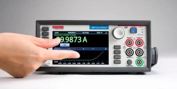
Калібратор-мультиметр Keithley 2450 американської компанії Кейтлі створений на основі і є новітнім продовженням лінійки джерел-вимірників, що добре зарекомендували себе Keithley серії 2400. Прилад Keithley 2450 є гнучким чотириквадрантним джерелом струму і напруги в поєднанні з прецизійними вольтметрами і амперметрами. Цей представник четвертого покоління джерел-вимірників (SMU) Keithley пропонує чудову точність, дозвіл та надійність, які повністю відповідають тому, що Ви очікуєте отримати від приладів компанії Keithley. Графічний сенсорний екран та проста структура меню моделі Keithley 2450 забезпечують простоту налаштування та експлуатації цього калібратора-мультиметра.
Основні характеристики:
Роздільна здатність: 6,5 розрядів. Базова точність (DCV): 0,012%.
Voltage Specifications 1, 2
| Source | Measure3 | |||||
| Range | Resolution | Accuracy (23° ± 5°C) 1 Year ±(% setting + volts) |
Noise (RMS) (<10 Hz)6 | Resolution | Input Resistance | Accuracy (23° ± 5°C) 1 Year ±(% rdg. + volts) |
| 20.00000 mV | 500 nV | 0.100% + 200 μV | 1 μV | 10 nV | >10 GΩ | 0.100% + 150 μV |
| 200.0000 mV | 5 μV | 0.015% + 200 μV | 1 μV | 100 nV | >10 GΩ | 0.012% + 200 μV |
| 2.000000 V | 50 μV | 0.020% + 300 μV | 10 μV | 1 μV | >10 GΩ | 0.012% + 300 μV |
| 20.00000 V | 500 μV | 0.015% + 2.4 mV | 100 μV | 10 μV | >10 GΩ | 0.015% + 1 mV |
| 200.0000 V | 5 mV | 0.015% + 24 mV | 1 mV | 100 μV | >10 GΩ | 0.015% + 10 mV |
Current Specifications1, 2
| Source | Measure3 | |||||
| Range | Resolution | Accuracy (23° ±5°C)4 1 Year ±(% setting + amps) |
Noise (RMS) (<10 Hz)6 | Resolution | Voltage Burden | Accuracy (23° ±5°C) 1 Year ±(% rdg. + amps) |
| 10.00000 nA5 | 500 fA | 0.100% + 100 pA | 500 fA | 10 fA | <100 μV | 0.100% + 50 pA |
| 100.0000 nA5 | 5 pA | 0.060% + 150 pA | 500 fA | 100 fA | <100 μV | 0.060% + 100 pA |
| 1.000000 μA | 50 pA | 0.025% + 400 pA | 5 pA | 1 pA | <100 μV | 0.025% + 300 pA |
| 10.00000 μA | 500 pA | 0.025% + 1.5 nA | 40 pA | 10 pA | <100 μV | 0.025% + 700 pA |
| 100.0000 μA | 5 nA | 0.020% + 15 nA | 400 pA | 100 pA | <100 μV | 0.020% + 6 nA |
| 1.000000 mA | 50 nA | 0.020% + 150 nA | 5 nA | 1 nA | <100 μV | 0.020% + 60 nA |
| 10.00000 mA | 500 nA | 0.020% + 1.5 μA | 40 nA | 10 nA | <100 μV | 0.020% + 600 nA |
| 100.0000 mA | 5 μA | 0.025% + 15 μA | 100 nA | 100 nA | <100 μV | 0.025% + 6 μA |
| 1.000000 A | 50 μA | 0.067% + 900 μA | 3 μA | 1 μA | <100 μV | 0.030% + 500 μA |
Temperature Coefficient (0°–18°C and 28°–50°C) ±(0.15 × accuracy specification)/°C.
Notes
- Speed = 1 PLC.
- All specifications are guaranteed with output ON.
- Accuracies apply to 2- and 4-wire mode when properly zeroed.
- For sink mode, 1 μA to 100 mA range accuracy is ±(0.15% + offset × 4). For 1A range, accuracy is ±(1.5% + offset × 8).
- Rear panel triax connections only.
- Typical noise (RMS) <10 Hz
Resistance Measurement Accuracy (Local or Remote Sense)1, 2
| Source | Measure3 | |||||
| Range | Default Resolution3 | Default Test Current | Normal Accuracy (23°C ±5°C) 1 Year, ±(% rdg. + ohms) |
Enhanced Accuracy4(23°C ±5°C) 1 Year, ±(% rdg. + ohms) |
||
| <2.000000 Ω5 | 1 μΩ | User defined | Source.IACC + Meas.VACC | Meas.IACC + Meas.VACC | ||
| 20.00000 Ω | 10 μΩ | 100 mA | 0.098% + 0.003 Ω | 0.073% + 0.001 Ω | ||
| 200.0000 Ω | 100 μΩ | 10 mA | 0.077% + 0.03 Ω | 0.053% + 0.01 Ω | ||
| 2.000000 kΩ | 1 mΩ | 1 mA | 0.066% + 0.3 Ω | 0.045% + 0.1 Ω | ||
| 20.00000 kΩ | 10 mΩ | 100 μA | 0.063% + 3 Ω | 0.043% + 1 Ω | ||
| 200.0000 kΩ | 100 mΩ | 10 μA | 0.065% + 30 Ω | 0.046% + 10 Ω | ||
| 2.000000 MΩ | 1 Ω | 1 μA | 0.110% + 300 Ω | 0.049% + 100 Ω | ||
| 20.00000 MΩ | 10 Ω | 1 μA | 0.110% + 1 kΩ | 0.052% + 500 Ω | ||
| 200.0000 MΩ | 100 Ω | 100 nA | 0.655% + 10 kΩ | 0.349% + 5k Ω | ||
| >200.000000 Ω5 | - | User defined | Source.IACC + Meas.VACC | Meas.IACC + Meas.VACC | ||
| Temperature Coefficient (0°–18°C and 28°–50°C) | ±(0.15 × accuracy specification)/°C. |
| Source Current, Measure Resistance Mode | Total uncertainty = Isource accuracy + Vmeasure accuracy (4-wire remote sense). |
| Source Voltage, Measure Resistance Mode | Total uncertainty = Vsource accuracy + Imeasure accuracy (4-wire remote sense). |
| Guard Output Impedance | 0.5 Ω (DC) in ohms mode. |
Notes
- All specifications are guaranteed with output ON.
- Accuracies apply to 2- and 4-wire mode when properly zeroed.
- 6.5 digit measure resolution
- Source readback enabled. Offset compensation ON.
- Source Current, Measure Resistance or Source Voltage, Measure Resistance only. For best measurements, use rear panel triax connectors.
Operating Characteristics
| Max. Output Power | 20 W, four-quadrant source or sink operation. | ||||||||||||
| Source Limits | Vsource: ±21 V (≤ 1 A range), ±210 V (≤ 100 mA range). Isource: ±1.05 A (≤ 20 V range), ±105 mA (≤ 200 V range). |
||||||||||||
| Overrange | 105% of range, source and measure. | ||||||||||||
| Regulation | Voltage: Line: 0.01% of range. Load: 0.01% of range + 100 µV. Current: Line: 0.01% of range. Load: 0.01% of range + 100 pA. |
||||||||||||
| Source Limits | Voltage Source Current Limit: Bipolar current limit set with single value. Min. 10% of range. Current Source Voltage Limit: Bipolar voltage limit set with single value. Min. 10% of range. |
||||||||||||
| V-Limit / I-Limit Accuracy | Add 0.3% of setting and ±0.02% of reading to base specification. | ||||||||||||
| Overshoot | Voltage Source: <0.1% typical (full scale step, resistive load, 20 V range, 10 mA I-Limit. Current Source: <0.1% typical (1 mA step, RLoad = 10 kΩ, 20 V range). |
||||||||||||
| Range Change Overshoot | Overshoot into a fully resistive 100 kΩ load, 10 Hz to 20 MHz BW, adjacent ranges: 250 mV typical. | ||||||||||||
| Output Settling Time | Time required to reach 0.1% of final value after command is processed and output slew, 20 V range, 100 mA I-Limit: <200 µs typical. | ||||||||||||
| Maximum Slew Rate | 0.2 V/μs, 200 V range, 100 mA limit into a 2 kΩ load (typical). | ||||||||||||
| Over Voltage Protection | User selectable values, 5% tolerance. Factory default = none. | ||||||||||||
| Voltage Source Noise | Typical 10 Hz–1 MHz (RMS): 2 mV typical into a resistive load. | ||||||||||||
| Common Mode Voltage | 250 V DC. | ||||||||||||
| Common Mode Isolation | >1 GΩ, <1000 pF. | ||||||||||||
| Noise Rejection (typical) |
* Except lowest two current ranges ~90dB. |
||||||||||||
| Load Impedance | 20 nF typical (standard). Stable into 50 μF typical (High-C mode). High-C mode valid for ≥100 µA range s, ≥200 mV ranges. |
||||||||||||
| Max. Voltage Drop Between Force and Sense Terminals | 5 V. | ||||||||||||
| Max. Sense Lead Resistance | 1 MΩ for rated accuracy | ||||||||||||
| Sense Input Impedance | >10 GΩ. | ||||||||||||
| Guard Offset Voltage | <300 µV, typical |
System Measurement Speeds1
Reading Rates (readings/second) typical for 60 Hz (50 Hz):
Script (TSP) Programmed
| Measure | Source-Measure Sweep | |||||||
| NPLC/Trigger Origin | To Mem. | To GPIB | To USB | To LAN | To Mem | To GPIB | To USB | To LAN |
| 0.01 / Internal | 3130 (2800) | 2830 (2570) | 2825 (2600) | 2790 (2530) | 1710 (1620) | 1620 (1540) | 1630 (1540) | 1620 (1540) |
| 0.01 / External | 2170 (2050) | 2150 (2030) | 2170 (2040) | 2160 (1990) | 1670 (1590) | 1580 (1500) | 1590 (1510) | 1580 (1510) |
| 0.1 / Internal | 540 (460) | 530 (450) | 530 (450) | 530 (450) | 470 (410) | 460 (400) | 470 (400) | 470 (400) |
| 0.1 / External | 500 (430) | 490 (420) | 500 (430) | 500 (420) | 470 (400) | 460 (390) | 460 (400) | 460 (400) |
| 1.00 / Internal | 59 (49) | 58 (49) | 59 (49) | 59 (49) | 58 (48) | 58 (48) | 58 (48) | 58 (48) |
| 1.00 / External | 58 (48) | 57 (48) | 58 (48) | 58 (48) | 57 (48) | 57 (47) | 57 (48) | 57 (48) |
SCPI Programmed2
| Measure | Source-Measure Sweep | |||||||
| NPLC/Trigger Origin | To Mem. | To GPIB | To USB | To LAN | To Mem | To GPIB | To USB | To LAN |
| 0.01 / Internal | 3130 (2800) | 3060 (2760) | 3000 (2790) | 3010 (2710) | 1710 (1630) | 1610 (1600) | 1440 (1380) | 1690 (1590) |
| 0.01 / External | 2350 (2200) | 2320 (2170) | 2340 (2190) | 2320 (2130) | 1680 (1590) | 1560 (1570) | 1410 (1360) | 1660 (1560) |
| 0.1 / Internal | 540 (460) | 540 (450) | 540 (460) | 540 (450) | 470 (410) | 470 (410) | 450 (390) | 470 (410) |
| 0.1 / External | 510 (440) | 510 (430) | 510 (440) | 510 (430) | 470 (400) | 470 (400) | 450 (390) | 470 (400) |
| 1.00 / Internal | 59 (49) | 59 (49) | 59 (49) | 59 (49) | 58 (48) | 58 (48) | 57 (48) | 58 (48) |
| 1.00 / External | 58 (49) | 58 (49) | 58 (49) | 58 (49) | 58 (48) | 58 (48) | 57 (47) | 58 (48) |
General Characteristics (default mode unless specified)
| Factory Default Standard Power-Up | SCPI Mode | ||||||||||||||
| Source Output Modes | Fixed DC Level, Memory/Configuration List (mixed function), Stair (linear and log). | ||||||||||||||
| Source Memory List | 100 points max. (SCPI 2400 Mode only). | ||||||||||||||
| Memory Buffer | >250,000 readings. Includes selected measured value(s) and time stamp. | ||||||||||||||
| Real-Time Clock | Lithium battery backup (3 yr. + battery life). | ||||||||||||||
| Remote Interfaces |
|
||||||||||||||
| Digital I/O Interface: |
|
||||||||||||||
| Programmability | SCPI or TSP command sets. | ||||||||||||||
| TSP Mode | Embedded Test Script Processor (TSP) accessible from any host interface. | ||||||||||||||
| IP Configuration | Static or DHCP. | ||||||||||||||
| Expansion Interface | The TSP-Link expansion interface allows TSP enabled instruments to trigger and communicate with each other. | ||||||||||||||
| LXI Compliance | 1.5 LXI Device Specification 2016. | ||||||||||||||
| Display | 5 inch capacitive touch, color TFT WVGA (800×480) with LED backlight. | ||||||||||||||
| Input Signal Connections | Front: Banana. Rear: Triaxial (3-lug). | ||||||||||||||
| Interlock | Active High Input. | ||||||||||||||
| Cooling | Forced air, variable speed. | ||||||||||||||
| Over Temperature Protection | Internally sensed temperature overload puts unit in standby mode. | ||||||||||||||
| Power Supply | 100 V to 240 V RMS, 50–60 Hz (automatically detected at power up). | ||||||||||||||
| VA Rating | 190 volt-amps max. | ||||||||||||||
| Altitude | Maximum 2000 meters above sea level. | ||||||||||||||
| EMC | Conforms to European Union EMC Directive. | ||||||||||||||
| Safety | NRTL listed to UL61010-1 and UL61010-2-30. Conforms with European Union Low Voltage Directive. | ||||||||||||||
| Vibration | MIL-PRF-28800F Class 3 Random. | ||||||||||||||
| Warm-Up | 1 hour to rated accuracies. | ||||||||||||||
| Dimensions | With bumpers and handle: 106 mm high × 255 mm wide × 425 mm deep (4.18 in × 10.05 in × 16.75 in). Without bumpers and handle: 88 mm high × 213 mm wide × 403 mm deep (3.46 in × 8.39 in × 15.87 in.) |
||||||||||||||
| Weight | With bumpers and handle: 4.04 kg (8.9 lbs.). Without bumpers and handle: 3.58 kg (7.9 lbs.). |
||||||||||||||
| Environment | Operating: 0° to 50 °C, 70% R.H. up to 35 °C. Derate 3% R.H./°C, 35° to 50 °C. Storage: –25 °C to 65 °C. |
||||||||||||||
| Accessories Supplied | Test Leads, USB Cable, Ethernet/TSP Cable, Interlock Adapter, Power Cord, Quick Start Guide. |
Області застосування:
- напівпровідникові прилади
- світлодіоди
- сонячні батареї
- наноматеріали та наноустрою, у тому числі графен
- друковані та гнучкі електронні пристрої
- акумулятори та інші електрохімічні пристрої
- датчики
- біотехнології
Voltage Specifications 1, 2
| Source | Measure3 | |||||
| Range | Resolution | Accuracy (23° ± 5°C) 1 Year ±(% setting + volts) |
Noise (RMS) (<10 Hz)6 | Resolution | Input Resistance | Accuracy (23° ± 5°C) 1 Year ±(% rdg. + volts) |
| 20.00000 mV | 500 nV | 0.100% + 200 μV | 1 μV | 10 nV | >10 GΩ | 0.100% + 150 μV |
| 200.0000 mV | 5 μV | 0.015% + 200 μV | 1 μV | 100 nV | >10 GΩ | 0.012% + 200 μV |
| 2.000000 V | 50 μV | 0.020% + 300 μV | 10 μV | 1 μV | >10 GΩ | 0.012% + 300 μV |
| 20.00000 V | 500 μV | 0.015% + 2.4 mV | 100 μV | 10 μV | >10 GΩ | 0.015% + 1 mV |
| 200.0000 V | 5 mV | 0.015% + 24 mV | 1 mV | 100 μV | >10 GΩ | 0.015% + 10 mV |
Current Specifications1, 2
| Source | Measure3 | |||||
| Range | Resolution | Accuracy (23° ±5°C)4 1 Year ±(% setting + amps) |
Noise (RMS) (<10 Hz)6 | Resolution | Voltage Burden | Accuracy (23° ±5°C) 1 Year ±(% rdg. + amps) |
| 10.00000 nA5 | 500 fA | 0.100% + 100 pA | 500 fA | 10 fA | <100 μV | 0.100% + 50 pA |
| 100.0000 nA5 | 5 pA | 0.060% + 150 pA | 500 fA | 100 fA | <100 μV | 0.060% + 100 pA |
| 1.000000 μA | 50 pA | 0.025% + 400 pA | 5 pA | 1 pA | <100 μV | 0.025% + 300 pA |
| 10.00000 μA | 500 pA | 0.025% + 1.5 nA | 40 pA | 10 pA | <100 μV | 0.025% + 700 pA |
| 100.0000 μA | 5 nA | 0.020% + 15 nA | 400 pA | 100 pA | <100 μV | 0.020% + 6 nA |
| 1.000000 mA | 50 nA | 0.020% + 150 nA | 5 nA | 1 nA | <100 μV | 0.020% + 60 nA |
| 10.00000 mA | 500 nA | 0.020% + 1.5 μA | 40 nA | 10 nA | <100 μV | 0.020% + 600 nA |
| 100.0000 mA | 5 μA | 0.025% + 15 μA | 100 nA | 100 nA | <100 μV | 0.025% + 6 μA |
| 1.000000 A | 50 μA | 0.067% + 900 μA | 3 μA | 1 μA | <100 μV | 0.030% + 500 μA |
Temperature Coefficient (0°–18°C and 28°–50°C) ±(0.15 × accuracy specification)/°C.
Notes
- Speed = 1 PLC.
- All specifications are guaranteed with output ON.
- Accuracies apply to 2- and 4-wire mode when properly zeroed.
- For sink mode, 1 μA to 100 mA range accuracy is ±(0.15% + offset × 4). For 1A range, accuracy is ±(1.5% + offset × 8).
- Rear panel triax connections only.
- Typical noise (RMS) <10 Hz
Resistance Measurement Accuracy (Local or Remote Sense)1, 2
| Source | Measure3 | |||||
| Range | Default Resolution3 | Default Test Current | Normal Accuracy (23°C ±5°C) 1 Year, ±(% rdg. + ohms) |
Enhanced Accuracy4(23°C ±5°C) 1 Year, ±(% rdg. + ohms) |
||
| <2.000000 Ω5 | 1 μΩ | User defined | Source.IACC + Meas.VACC | Meas.IACC + Meas.VACC | ||
| 20.00000 Ω | 10 μΩ | 100 mA | 0.098% + 0.003 Ω | 0.073% + 0.001 Ω | ||
| 200.0000 Ω | 100 μΩ | 10 mA | 0.077% + 0.03 Ω | 0.053% + 0.01 Ω | ||
| 2.000000 kΩ | 1 mΩ | 1 mA | 0.066% + 0.3 Ω | 0.045% + 0.1 Ω | ||
| 20.00000 kΩ | 10 mΩ | 100 μA | 0.063% + 3 Ω | 0.043% + 1 Ω | ||
| 200.0000 kΩ | 100 mΩ | 10 μA | 0.065% + 30 Ω | 0.046% + 10 Ω | ||
| 2.000000 MΩ | 1 Ω | 1 μA | 0.110% + 300 Ω | 0.049% + 100 Ω | ||
| 20.00000 MΩ | 10 Ω | 1 μA | 0.110% + 1 kΩ | 0.052% + 500 Ω | ||
| 200.0000 MΩ | 100 Ω | 100 nA | 0.655% + 10 kΩ | 0.349% + 5k Ω | ||
| >200.000000 Ω5 | - | User defined | Source.IACC + Meas.VACC | Meas.IACC + Meas.VACC | ||
| Temperature Coefficient (0°–18°C and 28°–50°C) | ±(0.15 × accuracy specification)/°C. |
| Source Current, Measure Resistance Mode | Total uncertainty = Isource accuracy + Vmeasure accuracy (4-wire remote sense). |
| Source Voltage, Measure Resistance Mode | Total uncertainty = Vsource accuracy + Imeasure accuracy (4-wire remote sense). |
| Guard Output Impedance | 0.5 Ω (DC) in ohms mode. |
Notes
- All specifications are guaranteed with output ON.
- Accuracies apply to 2- and 4-wire mode when properly zeroed.
- 6.5 digit measure resolution
- Source readback enabled. Offset compensation ON.
- Source Current, Measure Resistance or Source Voltage, Measure Resistance only. For best measurements, use rear panel triax connectors.
Operating Characteristics
| Max. Output Power | 20 W, four-quadrant source or sink operation. | ||||||||||||
| Source Limits | Vsource: ±21 V (≤ 1 A range), ±210 V (≤ 100 mA range). Isource: ±1.05 A (≤ 20 V range), ±105 mA (≤ 200 V range). |
||||||||||||
| Overrange | 105% of range, source and measure. | ||||||||||||
| Regulation | Voltage: Line: 0.01% of range. Load: 0.01% of range + 100 µV. Current: Line: 0.01% of range. Load: 0.01% of range + 100 pA. |
||||||||||||
| Source Limits | Voltage Source Current Limit: Bipolar current limit set with single value. Min. 10% of range. Current Source Voltage Limit: Bipolar voltage limit set with single value. Min. 10% of range. |
||||||||||||
| V-Limit / I-Limit Accuracy | Add 0.3% of setting and ±0.02% of reading to base specification. | ||||||||||||
| Overshoot | Voltage Source: <0.1% typical (full scale step, resistive load, 20 V range, 10 mA I-Limit. Current Source: <0.1% typical (1 mA step, RLoad = 10 kΩ, 20 V range). |
||||||||||||
| Range Change Overshoot | Overshoot into a fully resistive 100 kΩ load, 10 Hz to 20 MHz BW, adjacent ranges: 250 mV typical. | ||||||||||||
| Output Settling Time | Time required to reach 0.1% of final value after command is processed and output slew, 20 V range, 100 mA I-Limit: <200 µs typical. | ||||||||||||
| Maximum Slew Rate | 0.2 V/μs, 200 V range, 100 mA limit into a 2 kΩ load (typical). | ||||||||||||
| Over Voltage Protection | User selectable values, 5% tolerance. Factory default = none. | ||||||||||||
| Voltage Source Noise | Typical 10 Hz–1 MHz (RMS): 2 mV typical into a resistive load. | ||||||||||||
| Common Mode Voltage | 250 V DC. | ||||||||||||
| Common Mode Isolation | >1 GΩ, <1000 pF. | ||||||||||||
| Noise Rejection (typical) |
* Except lowest two current ranges ~90dB. |
||||||||||||
| Load Impedance | 20 nF typical (standard). Stable into 50 μF typical (High-C mode). High-C mode valid for ≥100 µA range s, ≥200 mV ranges. |
||||||||||||
| Max. Voltage Drop Between Force and Sense Terminals | 5 V. | ||||||||||||
| Max. Sense Lead Resistance | 1 MΩ for rated accuracy | ||||||||||||
| Sense Input Impedance | >10 GΩ. | ||||||||||||
| Guard Offset Voltage | <300 µV, typical |
System Measurement Speeds1
Reading Rates (readings/second) typical for 60 Hz (50 Hz):
Script (TSP) Programmed
| Measure | Source-Measure Sweep | |||||||
| NPLC/Trigger Origin | To Mem. | To GPIB | To USB | To LAN | To Mem | To GPIB | To USB | To LAN |
| 0.01 / Internal | 3130 (2800) | 2830 (2570) | 2825 (2600) | 2790 (2530) | 1710 (1620) | 1620 (1540) | 1630 (1540) | 1620 (1540) |
| 0.01 / External | 2170 (2050) | 2150 (2030) | 2170 (2040) | 2160 (1990) | 1670 (1590) | 1580 (1500) | 1590 (1510) | 1580 (1510) |
| 0.1 / Internal | 540 (460) | 530 (450) | 530 (450) | 530 (450) | 470 (410) | 460 (400) | 470 (400) | 470 (400) |
| 0.1 / External | 500 (430) | 490 (420) | 500 (430) | 500 (420) | 470 (400) | 460 (390) | 460 (400) | 460 (400) |
| 1.00 / Internal | 59 (49) | 58 (49) | 59 (49) | 59 (49) | 58 (48) | 58 (48) | 58 (48) | 58 (48) |
| 1.00 / External | 58 (48) | 57 (48) | 58 (48) | 58 (48) | 57 (48) | 57 (47) | 57 (48) | 57 (48) |
SCPI Programmed2
| Measure | Source-Measure Sweep | |||||||
| NPLC/Trigger Origin | To Mem. | To GPIB | To USB | To LAN | To Mem | To GPIB | To USB | To LAN |
| 0.01 / Internal | 3130 (2800) | 3060 (2760) | 3000 (2790) | 3010 (2710) | 1710 (1630) | 1610 (1600) | 1440 (1380) | 1690 (1590) |
| 0.01 / External | 2350 (2200) | 2320 (2170) | 2340 (2190) | 2320 (2130) | 1680 (1590) | 1560 (1570) | 1410 (1360) | 1660 (1560) |
| 0.1 / Internal | 540 (460) | 540 (450) | 540 (460) | 540 (450) | 470 (410) | 470 (410) | 450 (390) | 470 (410) |
| 0.1 / External | 510 (440) | 510 (430) | 510 (440) | 510 (430) | 470 (400) | 470 (400) | 450 (390) | 470 (400) |
| 1.00 / Internal | 59 (49) | 59 (49) | 59 (49) | 59 (49) | 58 (48) | 58 (48) | 57 (48) | 58 (48) |
| 1.00 / External | 58 (49) | 58 (49) | 58 (49) | 58 (49) | 58 (48) | 58 (48) | 57 (47) | 58 (48) |
General Characteristics (default mode unless specified)
| Factory Default Standard Power-Up | SCPI Mode | ||||||||||||||
| Source Output Modes | Fixed DC Level, Memory/Configuration List (mixed function), Stair (linear and log). | ||||||||||||||
| Source Memory List | 100 points max. (SCPI 2400 Mode only). | ||||||||||||||
| Memory Buffer | >250,000 readings. Includes selected measured value(s) and time stamp. | ||||||||||||||
| Real-Time Clock | Lithium battery backup (3 yr. + battery life). | ||||||||||||||
| Remote Interfaces |
|
||||||||||||||
| Digital I/O Interface: |
|
||||||||||||||
| Programmability | SCPI or TSP command sets. | ||||||||||||||
| TSP Mode | Embedded Test Script Processor (TSP) accessible from any host interface. | ||||||||||||||
| IP Configuration | Static or DHCP. | ||||||||||||||
| Expansion Interface | The TSP-Link expansion interface allows TSP enabled instruments to trigger and communicate with each other. | ||||||||||||||
| LXI Compliance | 1.5 LXI Device Specification 2016. | ||||||||||||||
| Display | 5 inch capacitive touch, color TFT WVGA (800×480) with LED backlight. | ||||||||||||||
| Input Signal Connections | Front: Banana. Rear: Triaxial (3-lug). | ||||||||||||||
| Interlock | Active High Input. | ||||||||||||||
| Cooling | Forced air, variable speed. | ||||||||||||||
| Over Temperature Protection | Internally sensed temperature overload puts unit in standby mode. | ||||||||||||||
| Power Supply | 100 V to 240 V RMS, 50–60 Hz (automatically detected at power up). | ||||||||||||||
| VA Rating | 190 volt-amps max. | ||||||||||||||
| Altitude | Maximum 2000 meters above sea level. | ||||||||||||||
| EMC | Conforms to European Union EMC Directive. | ||||||||||||||
| Safety | NRTL listed to UL61010-1 and UL61010-2-30. Conforms with European Union Low Voltage Directive. | ||||||||||||||
| Vibration | MIL-PRF-28800F Class 3 Random. | ||||||||||||||
| Warm-Up | 1 hour to rated accuracies. | ||||||||||||||
| Dimensions | With bumpers and handle: 106 mm high × 255 mm wide × 425 mm deep (4.18 in × 10.05 in × 16.75 in). Without bumpers and handle: 88 mm high × 213 mm wide × 403 mm deep (3.46 in × 8.39 in × 15.87 in.) |
||||||||||||||
| Weight | With bumpers and handle: 4.04 kg (8.9 lbs.). Without bumpers and handle: 3.58 kg (7.9 lbs.). |
||||||||||||||
| Environment | Operating: 0° to 50 °C, 70% R.H. up to 35 °C. Derate 3% R.H./°C, 35° to 50 °C. Storage: –25 °C to 65 °C. |
||||||||||||||
| Accessories Supplied | Test Leads, USB Cable, Ethernet/TSP Cable, Interlock Adapter, Power Cord, Quick Start Guide. |